The first development board i came in contact with was the Raspberry Pi, a few years ago. After building a tablet and a home automation system based on that board, i came across Arduino.
This because i had a work project that had to boot instantly (raspberry boot time is longer than a minute). It was a counting system for a conveyor, that can send the counted data to a server by ethernet.
Arduino is different of Raspberry, first because of the programming language. For Raspberry the main programming language is Python, while for Arduino is C, the other main difference is that Raspberry uses an operating system, while arduino only runs C programs, it does not run an operating system. Arduino bassicly a single chip microcontroller.
The main advantage of this board over Raspberry is that this have 6 analog ports, without any analog-to-digital converter.
After a few weeks of playing with arduino, i finished the counter project, and i learn a lot about this board, but what sparked my interest was connecting a Nokia 3310 LCD and display a text.
You can find more information about this here: http://playground.arduino.cc/Code/PCD8544
Here is the pinout diagram:

As you can see, in order to make the display to work properly, i had to solder a 10 uf capacitor between the Vout and GND pins. However on some lcd models that capacitor is not really necessary.
While i searched for more details about the atmega 328 (the arduino microcontroller) i found the Reduino core:

It is just like a Arduino uno board, but as basic as possible, with the Atmega cpu and the crystal. Also this board can be powered with no more than 5 volts.
To program it it is necessary to connect it to an arduino uno board:

It is perfect for small devices, or automation systems where the space is very small.
After i ordered several of this small boards (they are also very cheap), and because i had a spare Nokia 3310 lcd, i decided to create a small portable multimeter.
This is possible thanks to the built in analog inputs which can directly measure voltage up to 5V.
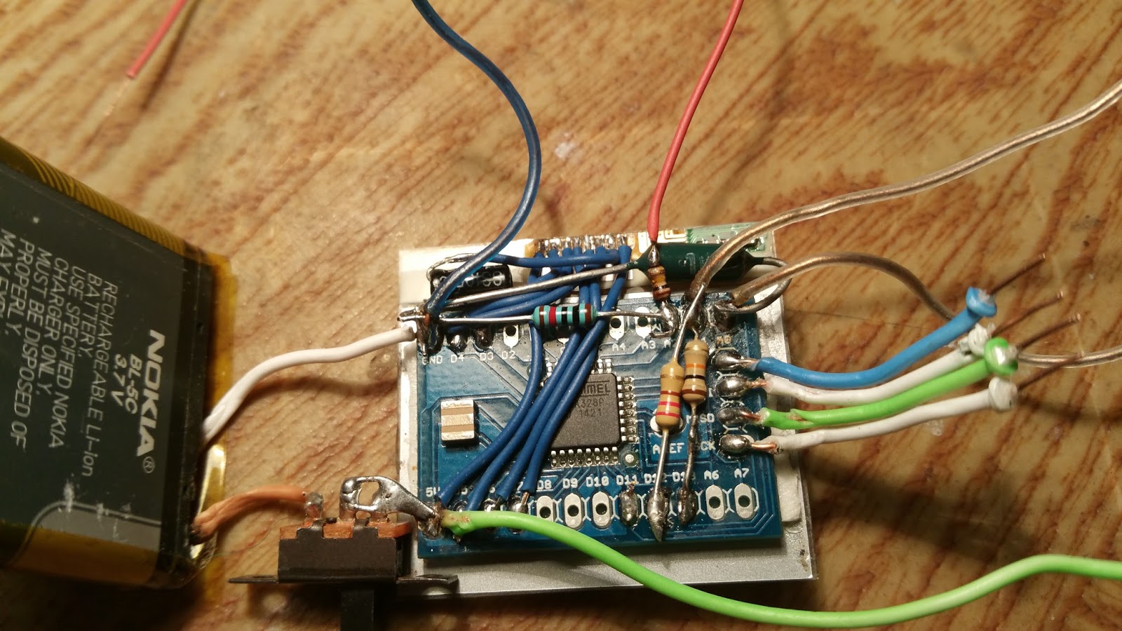
So i got a BL-5C Nokia battery to power the reduino board, (it does not deliver 5 volts, but it power the arduino and the nokia lcd quite well).
A small switch is connected to the + of the battery in order to turn it on/off . The 4 wires are plug in the arduino uno for reprogramming. Here are a few pictures of the building states.


1 Ohmmeter
Arduino can measure, with the analog inputs, the voltage at the middle of two resistors.
The schematic is very simple:

The arduino reads the voltage at the selected analog pin (A0). This voltage cross the resistor which is being measured.
You can find the source code of the ohmmeter on google. Here is one example: http://www.circuitbasics.com/arduino-ohm-meter/
What i did was to modify the code according to the voltage supplied by the battery (arduino works with 5V, but my battery can supply only 3.7 to 4 volts), and add some lines to display the value of the resistor on the nokia LCD.
2. Measure capacitors
After the the the small device could measure resistors, i decided to enhance it further by adding the posibility to measure capacitors.
The working principle is by measure the charging time of the capacitor.
The schematic and the source code are from here: https://www.arduino.cc/en/Tutorial/CapacitanceMeter
I modified the code, as was the case of the ohmmeter, and combine the two programs into one and upload them in the Reduino.
3. VoltmeterAfter the the the small device could measure resistors, i decided to enhance it further by adding the posibility to measure capacitors.
The working principle is by measure the charging time of the capacitor.
The schematic and the source code are from here: https://www.arduino.cc/en/Tutorial/CapacitanceMeter
I modified the code, as was the case of the ohmmeter, and combine the two programs into one and upload them in the Reduino.
The principle is simple since it is possible to measure voltage directly with the analog inputs. However there is the maximum 5V limit that can be applied to the input. So i used a 100 K ohm resistor. Here is the diagram:

The source code can be found here: https://www.arduino.cc/en/Tutorial/ReadAnalogVoltage
Again i modified the code to display the data on the nokia LCD and combine this code withe the first two, and the end result is a portable multimeter, which work quite good (there are limits in its accuracy), but for a quick measure is good, and very portable.
Here is a video with the multimeter in action:
This is the first version, i am going to make a plastic case for it and some sockets for probes.
Hey. Excellent device . It has long been looking for such a device . Share please Arduino sketch.
ReplyDeleteMy sketch is based on a combination of other sketches that you can easily find on google. Just search for them.
DeleteI'm glad you like it
ReplyDeleteWhere did you buy this board?
ReplyDeleteI would like to get a couple of them
Thank you
Jeffrey Stuart